Standard & Smart 8S BMS wiring tutorial
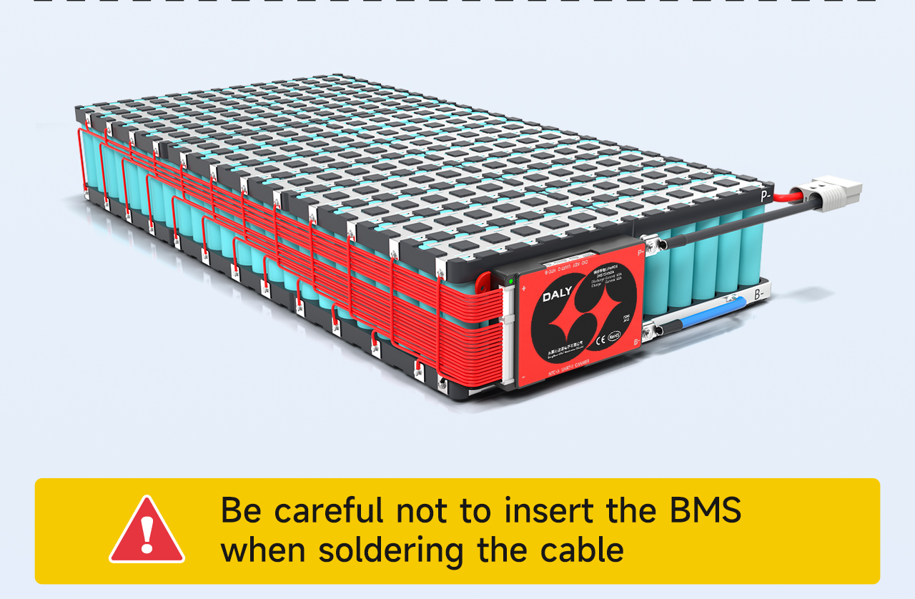
Take 24 series and 12 parallel 18650 battery pack as an example
Be careful not to insert the BMS when soldering the cable
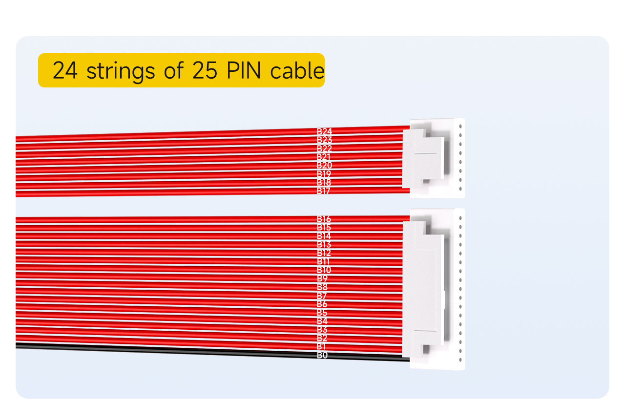
Ⅰ. Mark the order of sampling lines
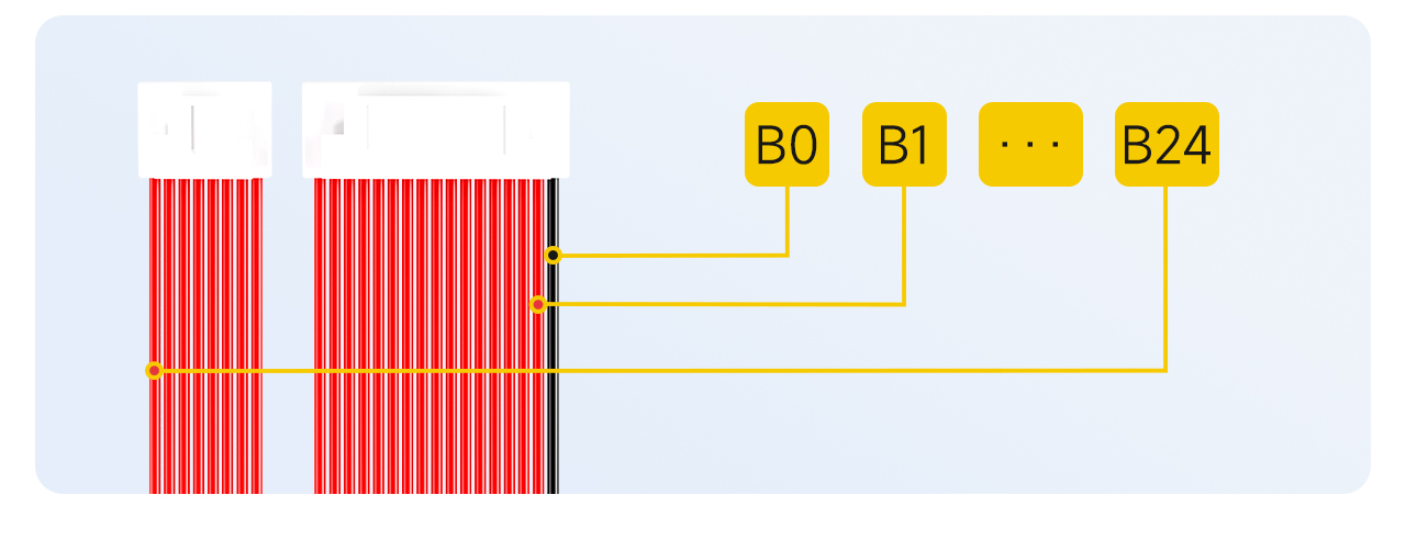
24 strings of 25PIN cable
Note: The default sampling cable for 24-string BMS configuration is 25PIN.
1. Mark the black cable as B0.
2. The first red cable next to the black cable is marked as B1
... (and so on, marked sequentially)
25. Until the last red cable, marked as B24.
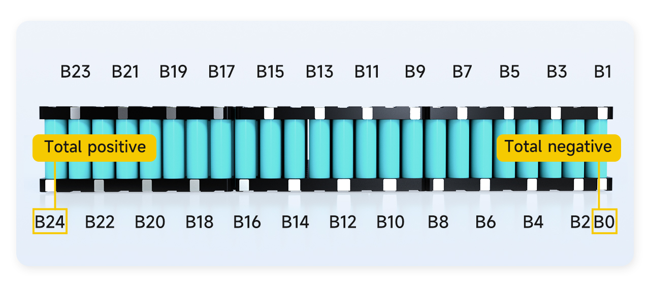
Ⅱ. Mark the order of battery welding points
Find the position of the corresponding welding point of the cable, first mark the position of the corresponding point on the battery
1. The total negative pole of the battery pack is marked as B0
2. The connection between the positive pole of the first string of batteries and the negative pole of the second string of batteries is marked as B1
3. The connection between the positive pole of the second string of batteries and the negative pole of the third string of batteries is marked as B2
... (and so on)
24. The connection between the positive pole of the 23th battery string and the negative pole of the 24th battery string is marked as B23.
25. The positive electrode of the 24th battery string is marked as B24.
Note: Because the battery pack has a total of 24 strings, B24 is also the total positive pole of the battery pack. If B24 is not the total positive stage of the battery pack, it proves that the order of marking is wrong, and it must be checked and marked again.
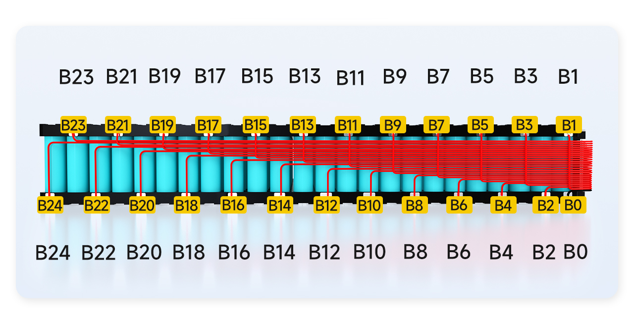
Ⅲ. Soldering and wiring
1. The B0 of the cable is soldered to the B0 position of the battery.
2. The cable B1 is soldered to the B1 position of the battery.
... (and so on, welding in sequence)
25. The cable B24 is soldered to the B24 position of the battery.
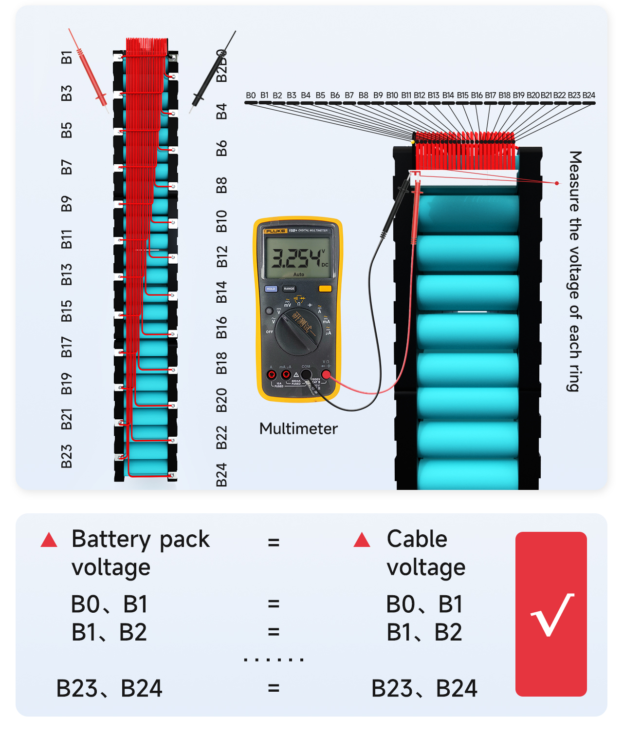
Ⅳ. Detection voltage
Measure the voltage between adjacent cables with a multimeter to confirm that the correct voltage is collected by the cables.
1. Measure whether the voltage of the cable B0 to B1 is equal to the voltage of the battery pack B0 to B1. If it is equal, it proves that the voltage collection is correct. If not, it proves that the collection line is weakly welded, and the cable needs to be re-welded. By analogy, measure whether the voltages of other strings are collected correctly.
2. The voltage difference of each string should not exceed 1V. If it exceeds 1V, it means that there is a problem with the wiring, and you need to repeat the previous step for detection.
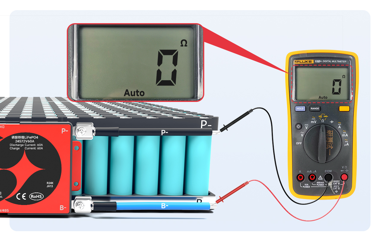
Ⅴ. Detection of BMS quality
! Always make sure the correct voltage is detected before plugging in the BMS!
Adjust the multimeter to the internal resistance level and measure the internal resistance between B- and P-. If the internal resistance is connected, it proves that the BMS is good.
Note: You can judge the conduction by looking at the internal resistance value. The internal resistance value is 0Ω, which means conduction. Due to the error of the multimeter, generally less than 10mΩ means conduction; you can also adjust the multimeter to the buzzer. A beeping sound can be heard.
Notice:
1. The BMS with soft switch needs to pay attention to the conduction of the switch when the switch is closed.
2. If the BMS is not conducting, please stop the next step and contact the sales staff for processing.
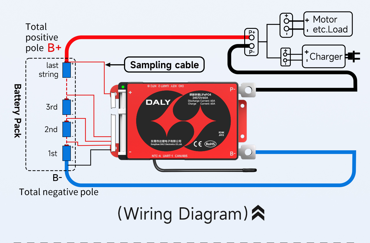
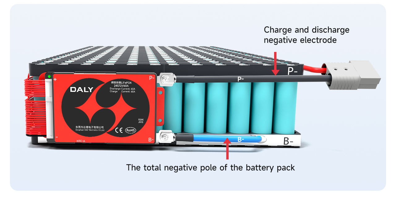
Ⅵ. Connect the output line
After ensuring that the BMS is normal, solder the blue B- wire on the BMS to the total negative B- of the battery pack. The P-line on the BMS is soldered to the negative pole of charge and discharge.
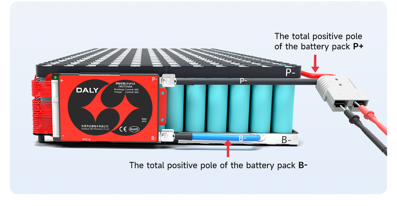
After welding, check whether the voltage of the over BMS is consistent with the battery voltage.
Detect over-board voltage: (B-, P+) voltage = (P-, P+) voltage
The positive pole of charging and discharging is directly connected with the total positive pole of the battery pack.
Note: The charging port and discharge port of the split BMS are separated, and the extra C-line (usually indicated by yellow) needs to be connected to the negative pole of the charger; the P-line is connected to the negative pole of the discharge.
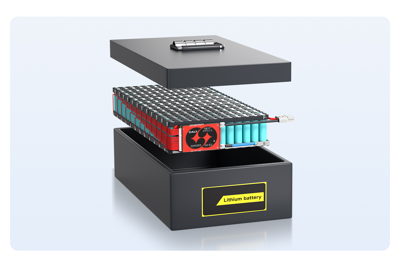
Finally, place the battery pack inside the battery box, and a finished battery pack is assembled